

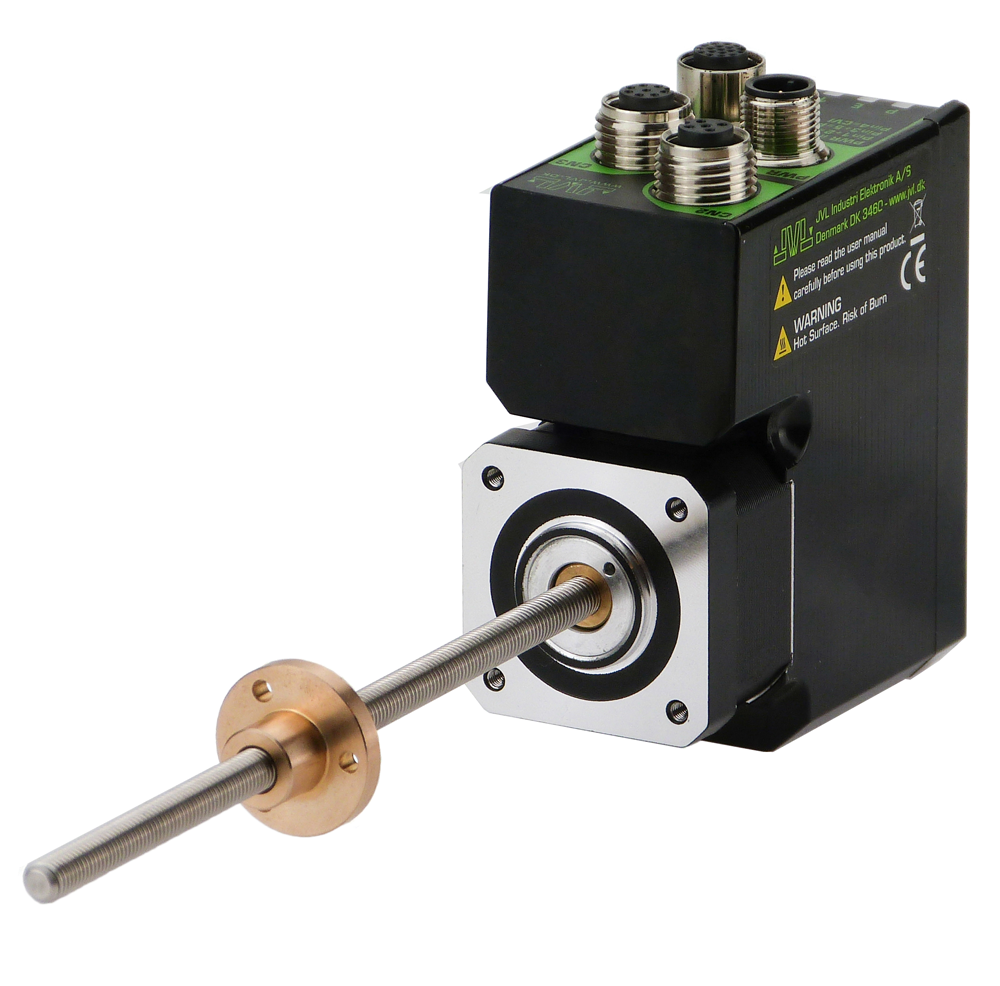
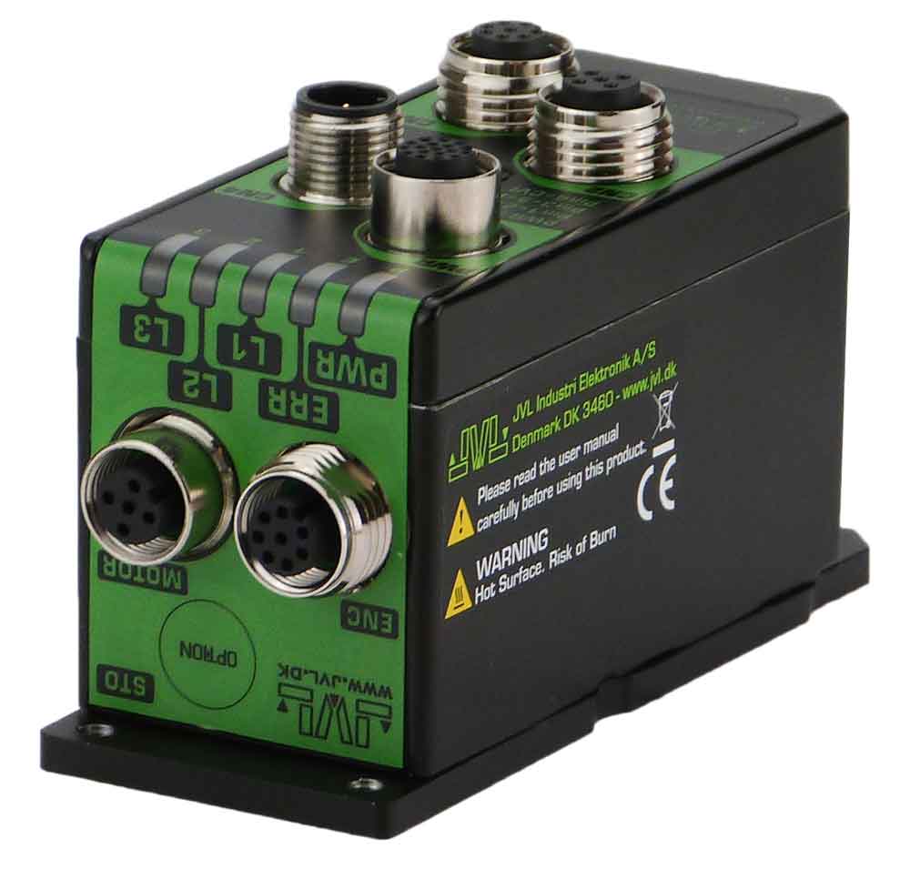
STO SIL3/PLe TÜV-approved integrated ServoStep NEMA 17-43
|
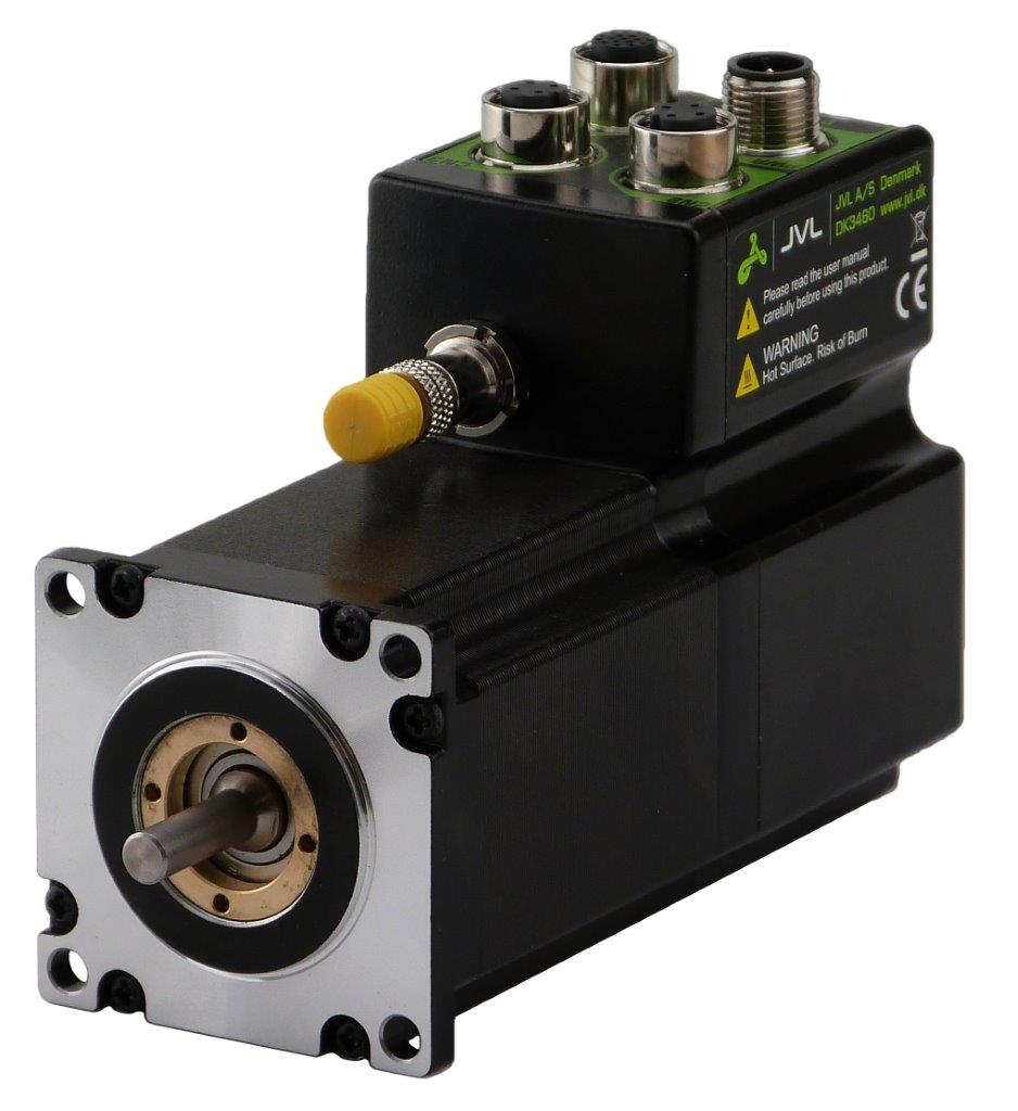
The STO Function can be used for disabling the energy to the motor. The motor will thereby be set in a state where it produces no torque.
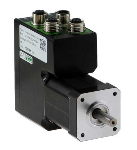
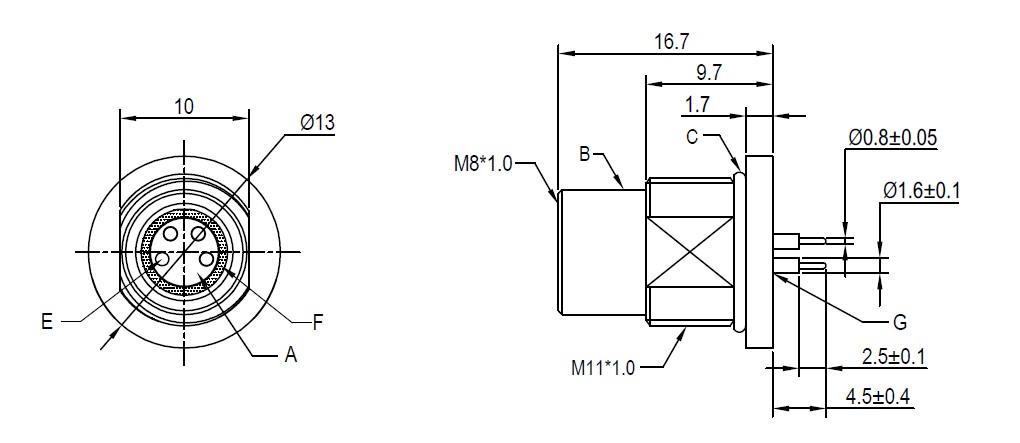
The STO function have its own input connector mounted at the front of the motor.
It is a two input system and it is required that both inputs are activated (applied with a voltage) before the motor is energized and can operate normally.
The STO is available for all ServoStep products.
To read more about MAC STO, click here. |
|
Why MIxyyz written on the Safety approved?
This is just a general short type code to the describe the whole range, so this certification covers a lot of different type numbers:
x = S,L (S=Rotary movement, traditional stepper MIS range and L=Linear actuator MIL range)
yy=17,23,34,43 (defines the motor flange size)
z = 0,1,2,3,4,5,6 (defines the maximum torque)
| Partnumber | Motor | STO Connector |
| MIS17xQ/R/S/T MIL17xQ/R/S/T User Manual |
  |
|
| MIS23x/Q/R/S/T User Manual |
 |
|
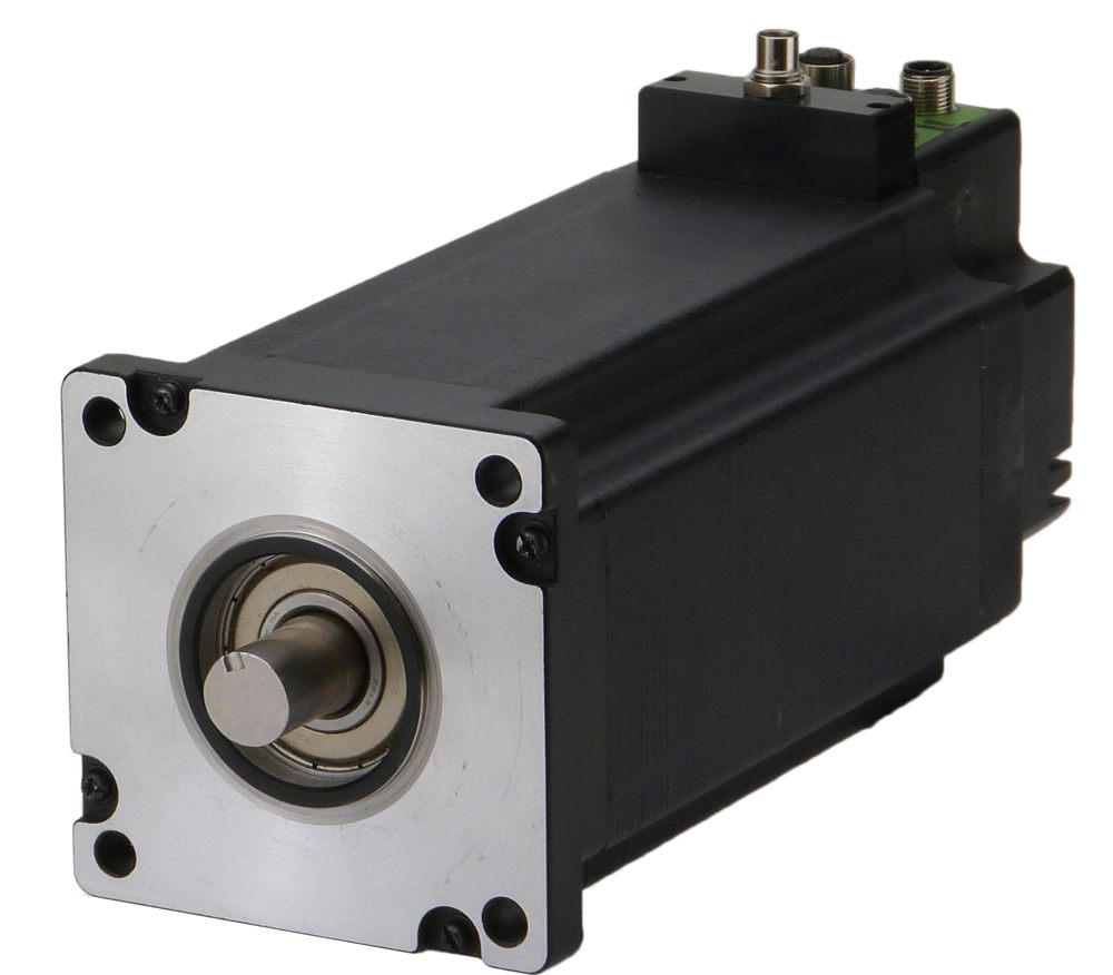
| MIS34x, MIL34x User Manual |
 |
|
| MIS43x User Manual |
 |
 |
|
SMC66x
Available with STO connector. The STO function is not yet approved by TUV but use same components as MIS17x and MIS23x that are TUV approved. User Manual |
 |
|
|
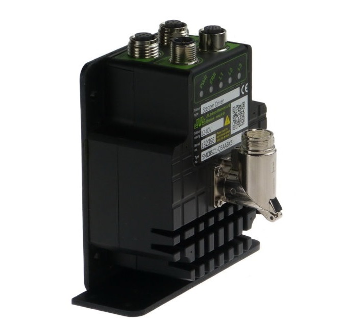
SMC85x
Under development. Please contact JVL. Available with STO connector. The STO function is not yet approved by TUV but use same components as MIS34x that are TUV approved. Please notice only foot mount possible (DIN mounting not possible) User Manual |
 |
|
|
MIS17/23 integrated motor with SMC67 PCBA
TÜV SÜD certification pending for STO HW connector and safety over Ethernet SIL3 / PLe
|
||
|
SMC67 PCBA or in a box
The TÜV SÜD certification for JVL integrated motors covers environmental qualification tests (shock & vibration, ingress protection, climatic, and electromagnetic) for specific enclosures. The certificate will lose its validity if the product is used in different environmental conditions or box or housing configurations.
When using the SMC67 PCBA or in box , the customer must independently demonstrate equivalence of their own enclosure and perform environmental testing to address any deviations. Such analyses and tests are not covered by the existing certification. Conclusion: The products can be marketed as prepared for SIL3 / PLe, but not as certified. The customer must certify the final product. However, documentation requirements will be reduced, as the PCBA and potentially the software are pre-certified. |
Accessories:
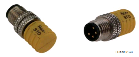
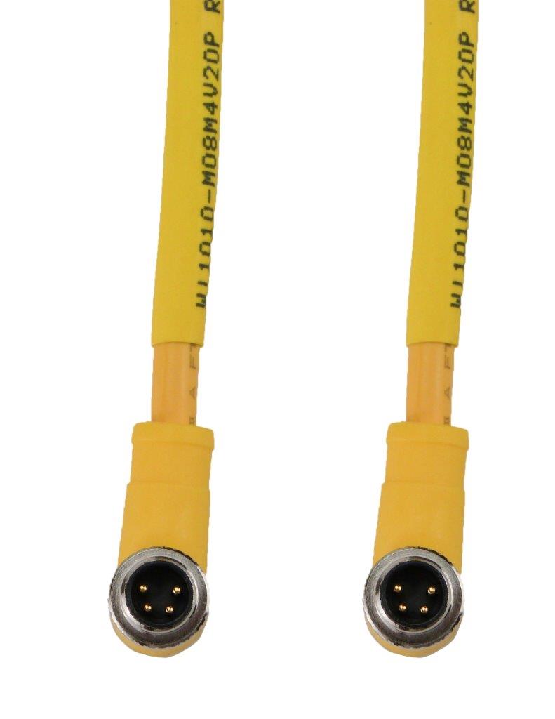
Disabling the STO function (NON-STO plug)
If the STO function is not needed the plug JVL type WI1010-M08M4SSTO must be inserted in the STO connector.
The need of this external plug to disable the STO function is to obtain a high safety level and make sure that no misunderstandings will occur concerning whether the STO function is active or not.
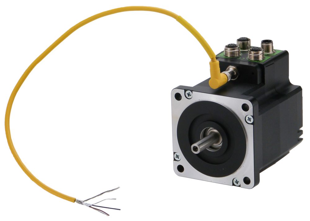
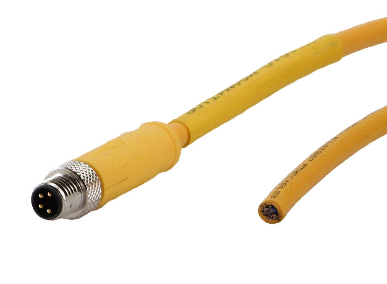
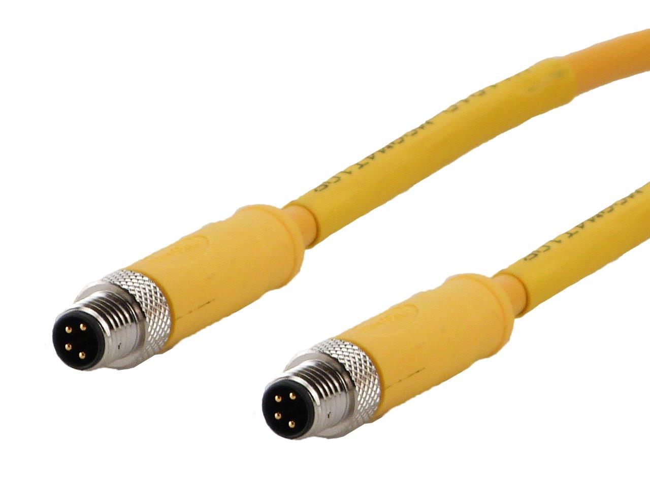
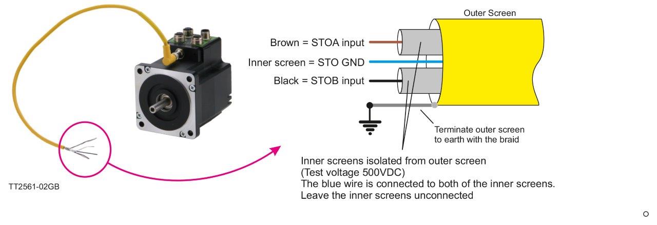
Standard cable
The standard cable is mandatory to use in applications where the TÜV approval is required.
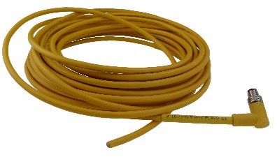
Part number: WI1010-M08M4V05P
How to connect and use the STO function:
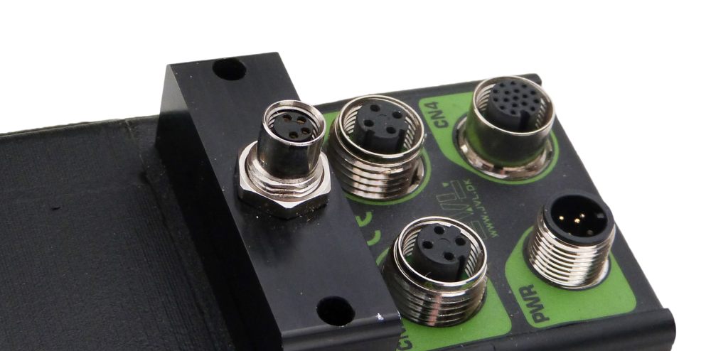
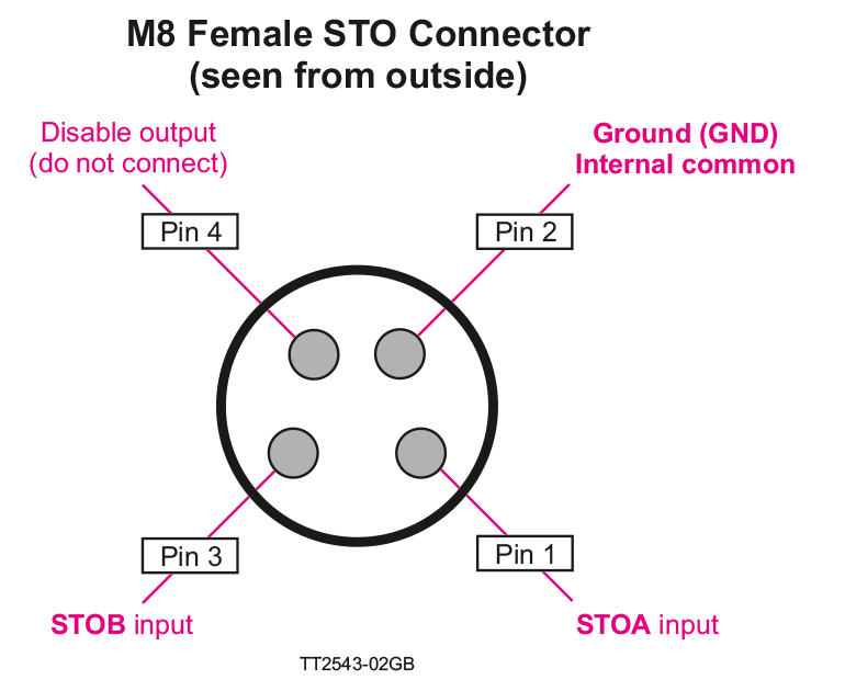
The STO connector contains the two enable inputs STOA and STOB. Both inputs must be applied nominal +24 VDC in order to energize the motor and make any motor movement possible.
If only one of the inputs is not applied +24 VDC the internal STO circuit will remove the energy from the motor. Please note: In a SIL3/PLe application, both channels must be controlled simultaneously.
The illustration below shows the pinout of the connector
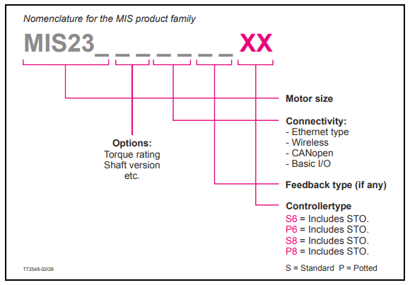
Ordering information:
ServoStep motors with the STO function installed are identified in the last two digits of the type number as seen below:
| European directives |
Machinery Directive (2006/42/EC) |
EN ISO 13849-1/2 | |
| EN IEC 62061 |
|||
| EN IEC 61800-5-2 |
|||
| EMC Directive (2014/30/EU) |
|||
| EN 61000-6-3 |
|||
| EN 61800-3 |
|||
| Low Voltage Directive (2014/35/EU) |
|||
| EN 61800-5-1 |
|||
| Safety standards |
Safety of Machinery |
EN ISO 13849-1/2, IEC 62061, IEC 60204-1 |
|
| Functional Safety |
IEC 61508-1/2, IEC 61800-5-2 |
||
| Safety function |
IEC 61800-5-2 |
IEC 60204-1 |
|
| Safe Torque Off (STO) |
Stop Category 0 |
||
| Safety performance |
ISO 13849-1 |
||
| Category | Cat 3 |
||
| Diagnostic Coverage | DCavg: 98,5 % (Medium) |
||
| Mean Time to Dangerous Failure (per channel) | MTTFd: 100 years (High) |
||
| PFHd | 4,29e-8/h |
||
| Performance Level | PLe |
||
| IEC 61508/IEC 62061 |
|||
| Safety Integrity Level | SIL 3, SIL CL3 |
||
| Probability of Dangerous Failure per Hour | PFHd: 1,38e-10/h (High Demand Mode) |
||
| Diagnostic Coverage | DC: 96 % |
||
| Safe Failure Fraction | SFF: 96 % |
||
| Common Cause Failure Factor | CCF 5 % |
||
| Hardware Fault Tolerance | HFT: 1 (1oo2) |
||
| Proof Test Interval T1 | 20 Years |
||
| Mission time TM | 20 Years |
||
| Reaction time |
Input to output response time | Maximum 8 ms. |
|
| Response time (internal fault) | Maximum 200 ms. |
||
SISTEMA:
The SISTEMA software utility provides developers and testers of safety-related machine controls with comprehensive support in the evaluation of safety in the context of EN ISO 13849-1.
Many companies use the SISTEMA libraries when designing a machine with several safety components. JVL offers for particular technologies continuously growing SISTEMA-Libraries. The libraries can be used with SISTEMA starting from version 1.1.1. Download the tool here Link to SISTEMA Library.
Your advantages:
- Fast calculation of the Performance Level
- Easy and fast access to safety relevant data
- Data for certified and standard components
- The tool is supported by many manufacturers


JVL A/S Bregnerødvej 127 DK-3460 Birkerød Denmark
Tel: +45 4582 4440 Fax: +45 4582 5550 E-mail: jvl@jvl.dk
Tel: +45 4582 4440 Fax: +45 4582 5550 E-mail: jvl@jvl.dk
