

Getting started and mechanical dimensions
Serial to wireless converter getting Started
Before using your Serial Port Adapter you must:
·Install your Serial Port Adapter. For more information, see Installation section.
·Configure your Serial Port Adapter. For more information, please read the Getting Started Serial Port Adapter. It is also possible to use the Serial Port Adapter Toolbox for easy test and configuration.
Installation
Before using your Serial Port Adapter it must be connected to its host system and it must be connected to a power supply. The installation differs slightly from model to model.
This chapter describes how to install your Serial Port Adapter.
This chapter describes how to install your Serial Port Adapter.
OEM Serial Port Adapters
If you are using the OEM Serial Port Adapter please refer to the "Electrical & Mechanical Datasheet” for the specific model, for installation instructions.
Rugged Serial Port Adapters
Mounting
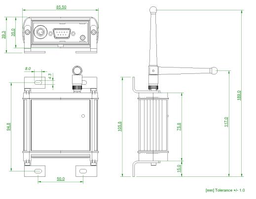
Figure 1. The Serial Port Adapter can be mounted using the mounting holes.
Rugged Serial Port Adapter must only be used with the antenna provided with the product. Using another antenna will violate the regulatory type approval. The product cannot be mounted inside a shielded enclosure.
Power Supply
The product shall have a power supply of 8-30 VDC, 1 W on pin 1 (-) and 2 (+) on the power connector. Use a female power connector 712 series from Binder.
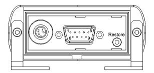
Figure 2. Power connector on the left side and the DSUB serial connector (male) in the middle.
Current consumption
Current consumption measured at 30V.
Mode
Value
Unit
Not connected
Connectable, discoverable
Average
17
mA
Not connected
Inquiry
Peak
31
mA
Connected
Idle
Average
18
mA
Connected
Transmitting@115.2 kbit/s
Average
24
mA
RS232
| Mode | Value | Unit | ||
| Not connected | Connectable, discoverable | Average | 17 | mA |
| Not connected | Inquiry | Peak | 31 | mA |
| Connected | Idle | Average | 18 | mA |
| Connected | Transmitting@115.2 kbit/s | Average | 24 | mA |
This model supports RS232 with a male 9-pin DSUB:
·Pin 1: NC, not connected
·Pin 2: RD, input, receive data
·Pin 3: TD, output, transmit data
·Pin 4: DTR, output, data terminal ready
·Pin 5: GND, ground
·Pin 6: DSR, input, data set ready
·Pin 7: RTS, output, request to send
·Pin 8: CTS, input, clear to send
·Pin 9: NC, not connected
The model is designed to operate as a DTE (Data Terminal Equipment). When connecting the Serial Port Adapter to a DCE (Data Communication Equipment), e.g. a modem, a regular modem cable, straight cable, shall be used. When connecting the Serial Port Adapter to another DTE, e.g. a PC, a crossover serial cable must be used. The crossover cable must have TD and RD crossed (pins 2-3 and 3-2), RTS and CTS crossed (pins 7-8 and 8-7) and optionally DTR and DSR crossed (pins 4-6 and 6-4).
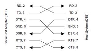
Figure 3. Crossover cable.
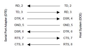
Figure 4. Straight cable
RS422
In this model, the same DSUB connector is used when using RS232, RS422 and RS485. However, in the case of RS422 and RS485, the pins have different meanings compared to RS232. For details please read the AT command specification document.
In the RS422 case, the following pinning is used:
In the RS422 case, the following pinning is used:
·Pin 1: R-, input, receiver
·Pin 2: T-, output, transmitter
·Pin 3: NC, not connected
·Pin 4: NC, not connected
·Pin 5: NC, not connected
·Pin 6: R+, input, receiver
·Pin 7: NC, not connected
·Pin 8: T+, output, transmitter
·Pin 9: NC, not connected
For four-wire RS422 multidrop, the following connection setup shall be used:
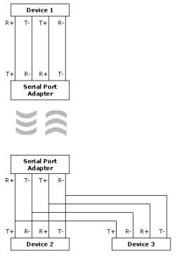
Figure 5. Four-wire RS422 connection setup.
Note: The definition of R+/R-,T+/T- may vary between manufacturers.
RS485
In the case of RS485, the same pinning as for RS422 is used, except that pins T- and R- must be connected externally and pins T+ and R+ must be connected externally to produce the signals T-/R- and T+/R+. For two-wire RS485 multidrop, the following connection setup shall be used: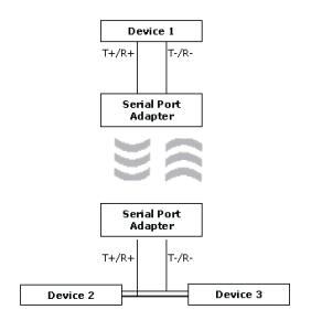
Figure 6. Two-wire RS485 connection setup.
Button and LED
If the restore button pressed during power on, the default serial settings as well as the default escape sequence are restored.
The status LED uses the following color indications.
The status LED uses the following color indications.
·Green: The current mode is data mode and no connection attempt is in progress.
·Orange: The current mode is AT mode.
·Purple: A connection attempt is in progress.
·Blue: A connection is currently active.
·Blue Blinking: A connection is active and data is transmitted or received over air.
·Red Blinking: Buffer overflow, parity or framing error detected on the UART.


JVL A/S Bregnerødvej 127 DK-3460 Birkerød Denmark
Tel: +45 4582 4440 Fax: +45 4582 5550 E-mail: jvl@jvl.dk
Tel: +45 4582 4440 Fax: +45 4582 5550 E-mail: jvl@jvl.dk
