

ATTENTION! Risk of overvoltage when used for motor power. Recommendation how to build a stable power supply for motor controllers
1. Protect power supply from overvoltage damage:
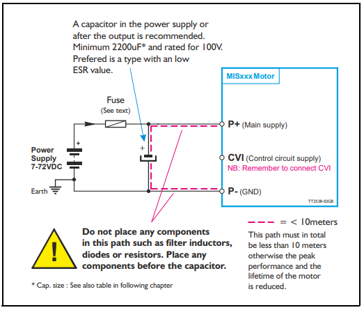
When a motor decelerates or brakes, energy will be generated, called back EMF. This results in a voltage increase across P+ and P- which can cause damage to the power supply. To avoid overvoltage, a blocking diode in series with P+ can be mounted to avoid damage of the PSU. A capacitor in the range 500 to 1000uF per 100W power supply, can also be mounted between the diode and motor to protect the motor or controller from over voltage.
2. Protect motor controller from overvoltage damage:
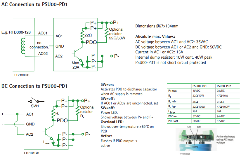
When a motor decelerates or brakes, energy will be generated, called back EMF. This results in a voltage increase across P+ and P- which can cause damage to the motor controller. To avoid overvoltage, a power dump resistor unit, like JVL PSU00-PD1 or PSU00-PD2, can be mounted to absorb the energy/over voltage. A very large capacitor can also be used to absorb short period spikes. Some power supplies have a large capacitor build in to absorb energy but often a switch mode power supply is used, which is only supplied with a small capacitor, and in that case an external capacitor is required when the motor is used for high speed and dynamic movements.
A JVL controller have a small overvoltage diode mounted, but typically to protect against short spikes, so an external resistor or capacitor should be mounted, when energy repeatedly are sent back to P+. If 24 or 48VDC power supply is used an external diode or resistor is required for full protection.
A JVL controller have a small overvoltage diode mounted, but typically to protect against short spikes, so an external resistor or capacitor should be mounted, when energy repeatedly are sent back to P+. If 24 or 48VDC power supply is used an external diode or resistor is required for full protection.
3. Two power supplies in series:
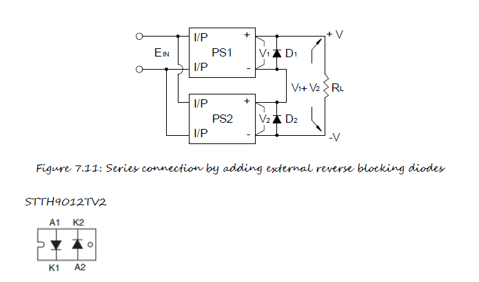
To increase the output voltage (current does not change), some power supplies can be coupled in series. If there is no reserve blocking diode in the power supply, an external blocking diode must be added to prevent damage to the power supply while starting up. The voltage rating of the external diode should be larger than V1+V2 as below figure.
4. Measure voltage correct to detect overvoltage that can damage PSU or controller:
You can measure possible overvoltage with the MacTalk scope function in a live application. You cannot measure overvoltage with a standard voltmeter (e.g. Fluke) because overvoltage sometimes only is a short spike of 10-500 mS, so an oscilloscope or the MacTalk scope function is needed to measure overvoltage. If you measure the voltage at the power supply, e.g. 20 meters from the motor, there is a risk that an overvoltage spike from the controller not to be measured correctly. So if you have a defect controller and considers overvoltage, always use the MacTalk scope function to measure the voltage inside the controller.
5. Capacitor needed?
A motor will always generate return energy when stopping or decelerating. This energy will increase the voltage, and should be absorbed into a power dump resistor or a capacitor, otherwise there is a risk of overvoltage damage to the power supply or the motor controller. It is often needed to do a test in the actual application if a blocking diode, capacitor or power dump resistor is needed. You cannot measure overvoltage with a standard voltmeter (e.g. Fluke) because overvoltage sometimes only is a short spike of 10-500 mS, so an oscilloscope or the MacTalk scope function is needed to measure overvoltage.
6. Cables:
1: All cables should be with shield, which must be connected to M12 housing
2: Shield from power cable must be connected to P- (Power ground at power supply)
3: We recommend that all motors are grounded together with a thick 2.5 square wire to the same point, typically P-
4: All motors should be connected directly to a power supply, to avoid junctions points.
5: All Ethernet cables should be with shield, which must be connected to M12 housing
6: All JVL cables are with shield and shield connected to M12 housing
7. Separation of CVI and P+
When using 24VDC for P+, it is possible to use the same power supply for P+ and CVI. This can be OK for many applications, but if the motor is generating back EMF when braking or being driven, the voltage at P+ will rise, causing the voltage at the common power supply for CVI and P+ to rise above the allowed maximum level for CVI. This can result in the electrical components in the motors CVI circuit to burn, and the motor will need to be shipped to JVL for repair.It is your responsibility, as machine builder/designer, to make sure that the voltage maximum levels are never exceeded at both P+ and CVI. If the motor brakes or is being driven, a separate supply for CVI is needed, and P+ must be protected according to above.


JVL A/S Bregnerødvej 127 DK-3460 Birkerød Denmark
Tel: +45 4582 4440 Fax: +45 4582 5550 E-mail: jvl@jvl.dk
Tel: +45 4582 4440 Fax: +45 4582 5550 E-mail: jvl@jvl.dk
