

SERCOS III - General Architecture
In order to achieve the throughput and jitter requirements required in the applications the interface is designed for, Sercos III operates primarily in a Master/Slave arrangement exchanging cyclic data between nodes. The Master initiates all data transmission during a Sercos real-time cycle. All data transmissions begin and end at the Master (circular).
Sercos III cycle
| Communication across a Sercos III network occurs in strict cyclic intervals. A cycle time is chosen by the user for a given application, ranging from 31.25 µs to 65 ms. Within each cycle, data is exchanged between Sercos III nodes using two types of telegrams: MDTs and ATs (see Telegram Types). |
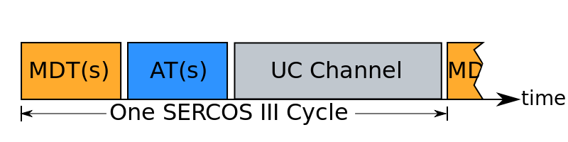
The basic Sercos III cycle |
|
After all MDTs and ATs are transmitted, Sercos III nodes allow the remaining time in the cycle to be used as an UC (Unified Communication) Channel, which can be used to exchange data using other formats, such as IP.
| The network remains available to UCC traffic until the next cycle begins, at which time the Sercos III nodes close the nodes to UCC traffic again. This is an important distinction. Sercos is purposely designed to provide open access at all ports for other protocols between cyclic real time messages. No tunneling is required. This provides the advantage that any Sercos III node is available, whether Sercos III is in cyclic mode or not, to use other protocols, such as TCP/IP, without any additional hardware to process tunneling. Sercos nodes are specified to provide a store and forward method of buffering non-Sercos messages should they be received at a node while cyclic communication is active. |
Telegrams
| Telegram format All Sercos III telegrams conform to the IEEE 802.3 & ISO/IEC 8802-3 MAC (Media Access Control) frame format. |
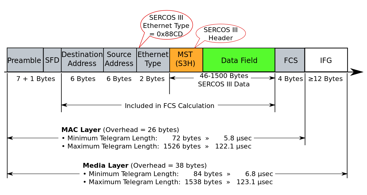 Sercos III Telegram Structure |
|
| Destination address The destination address for all Sercos III telegrams is always 0xFFFF FFFF FFFF (all 1s), which is defined as a broadcast address for Ethernet telegrams. This is because all telegrams are issued by the Master, and are intended for all Slaves on the network. |
||
| Source address The source address for all Sercos III telegrams is the MAC address of the Master, as it issues all telegrams. |
||
| Ethernet type A unique EtherType value has been assigned via the IEEE EtherType Field Registration Authority for Sercos III (0x88CD). |
||
| Sercos III header The beginning of the Ethernet-defined data field always begins with a Sercos III header, which contains control and status information unique to Sercos. |
||
| Sercos III data field The Sercos III header is followed by the Sercos III data field, which contains a configurable set of variables defined for each device in the network. |
||
Telegram types
Two main types of telegrams are used within the Sercos III Cycle. The Master Data Telegram (MDT), and the Acknowledge telegram (AT). Both telegram types are issued by the Master (control). The MDT contains information provided by the Master to Slaves. It is filled by the Master, and read by Slaves. The AT is issued by the Master, but actually populated by each Slave with their appropriate response data (feedback values, input states, etc.). More than one Slave uses the same AT, filling in its pre-determined area in the AT telegram, updating checksums, and then passing the telegram to the next device. This method reduces the impact of the Ethernet frame overhead on the performance of the network without compromising IEEE 802.3 & ISO/IEC 8802-3. The amount of data sent from the Master to Slaves, as well as the sum of the data returned by the Slaves, may exceed the 802.3-specified maximum 1500-byte data field size. To comply with this limit, Sercos III may use more than one MDT telegram in a cycle, as well as more than one AT telegram (up to 4 in each case).
Synchronization
| To achieve true hard real time characteristics, Sercos III, like Sercos I & II, uses a form of synchronization that depends upon a synchronization "mark” issued by the Master control at exact equidistant time intervals. All nodes in a Sercos Network use this telegram to synchronize all activities in the node. To account for variations in network components, delays are measured in the node-to-node transmissions during phase-up (initialization) of a Sercos network, and those values compensated for during normal operation. Unlike Sercos I & II, where a separate Master Sync Telegram, or MST is used for this purpose, Sercos III includes the MST in the first MDT transmitted. No separate telegram is issued. The time between two MSTs is exactly equal to the designated Sercos Cycle Time, tScyc. |
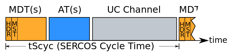 Sercos III Synchronization |
Physical and data link layers
|
Sercos III supports standard IEEE 802.3 & ISO/IEC 8802-3 100Base-TX or 100Base-FX (100 Mbit/s baseband) Full Duplex physical layer (PHY) entities. 802.3-compliant Media-Access Controller (MAC) sub-layers are used. Autonegotiation must be enabled on each PHY, but only 100Mbit full duplex is supported. Auto (MAU [Media Attachment Unit]-Embedded) Crossover is specified between the two Physical Medium Attachment (PMA) units present with a duplex port. These two units are referred to as the Primary Channel and Secondary Channel in the Sercos III specification. Dual interfaces are required (two duplex interfaces per device). Within the Sercos III specification the dual interfaces are referred to as P1 and P2 (Ports 1 and 2). |
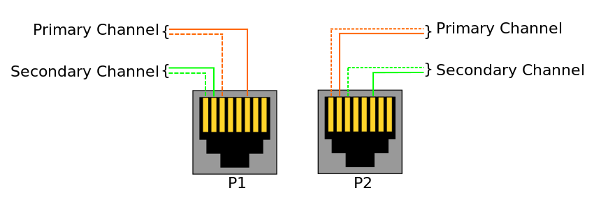 Sercos III Physical Interface Nomenclature |
Sercos III stack
All of the functionality required to configure a Sercos III interface is contained in a stack that is available in both "hard” and "soft” versions. The hard version is widely used for embedded applications (such as drives, I/O modules and micro-controller based motion control), where:
- It is important that the overhead of managing the Sercos III nodes not be placed upon the device processor.
- Nanosecond jitter is required.
The hardware stack is available in a number of different forms.[7] These currently include:
- A bit stream for Xilinx FPGAs for master and slave
- A bit stream for Altera FPGAs for master and slave
- A bit stream for Lattice Semiconductor FPGAs for master and slave
- A Net list for Xilinx FPGAs for master and slave
- A Net list for Altera FPGAs for master and slave
- A Net list for Lattice FPGAs for master and slave
- The "netX” multi-network controller chip from Hilscher, GmbH for master and slave
- The Anybus CC module from HMS Industrial Networks for slave
- The Sitara™ AM335x microprocessors from Texas Instruments for master and slave.
- Innovasic, Inc. announced to release a Sercos version based on their fido 5000 REM Switch chip.
The maximum jitter allowed with hard-stack-based Masters and Slaves is less than 1 µs. Using the above stacks yields a jitter similar to Sercos II (35-70 nanoseconds).
Sercos III also supports a "Soft Master”, using a completely software-based stack for the master interface.[8] Since the maximum jitter in such a configuration is dependent upon the operating system of the Master, the maximum jitter may be set by a variable for the Sercos III network when a Soft Master is employed.
For basic Slaves, such as I/O devices, EasySlave-IO, a license-free bitstream variant of the EasySlave is available.
Data consistency
A term usually associated with the IT enterprise, data consistency can also apply to real-time control (see for example Peer to Peer Communication). For this reason, Sercos III specifies that no data be overwritten (destroyed) during a transmission. Every slave on a network may access input and output data for every other slave on the network.
Addressing
Devices must support Ethernet’s MAC addressing, plus the Sercos III addressing. Other addressing schemes are optional.
Sercos III address
Each Sercos III device contains a numeric address used by other devices on the Sercos III network to exchange data. The address may be any whole integer from 1 to 511.
IP address
Sercos III does not use an IP address for its own operation. Whether a device contains an IP address or not is dependent on its support of other specifications, either independent (exclusive) of Sercos III operation, or via the UC (Unified Communication) Channel portion of the cycle.
Network topologies
The Sercos III specification defines two possible network topologies; Ring and Line. To those familiar with other networks, both of them may appear to be configured as a ring. All telegrams begin and end at the Master. The Full Duplex feature of the physical layer is used to achieve this.
Line topology
| A line topology is the simpler of the two possible arrangements, and provides no redundancy. However, this configuration saves the cost of one cable. In it, only one of the two interfaces on the Master is used. Telegrams are issued out of the transmit PMA on the Master’s active port. Either port on the Master may be the active one. Sercos III determines this during phase-up (initialization). The first Slave receives the telegrams on the connected interface’s receive PMA, modifies them as required, and issues them out on the transmit PMA of the second interface. Each cascading Slave does likewise until the last Slave in the Line is reached. That Slave, detecting no Sercos III connection on its second port, folds the telegram back on the receiving interface’s transmit port. The telegram then makes it way through each Slave back to the Master. Note the last Slave also emits all Sercos III telegrams on its second port, even though no Sercos III connection is detected. This is for snooping, ring closures (see below), as well as hot-plugging. Keep in mind that since the Ethernet destination field in all Sercos III telegrams is the broadcast address of 0xFFFF FFFF FFFF (all 1s), all telegrams issued from this open port will be seen by other devices as broadcast telegrams. This behavior is by design, and cannot be disabled. To avoid taxing networks attached to an open Sercos port, an IP-Switch can be used, or alternately a managed Ethernet switch programmed to block broadcast telegrams received from the Sercos port can be used. Starting with Sercos III specification version 1.3.1 the connection of Industrial Ethernet devices is supported where devices work with 20 ms cycle time in communication phase 0 (CP 0). |
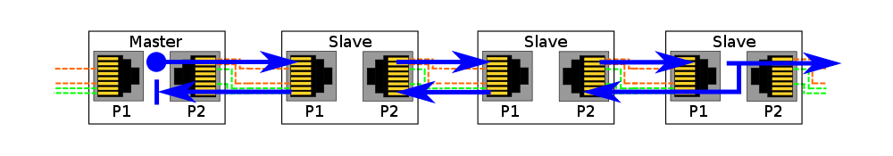 Sercos III Line Topology |
| Ring topology |
|
A ring topology simply closes the network by attaching the unused port on the last device in a ring back to the unused port on the Master. When the Sercos III Master senses that a ring exists, it sets up two counter-rotating telegrams. The same data is issued simultaneously out of the transmit PMAs of both ports on the Master. From there both telegrams are managed essentially identically as they make their way through each Slave, ending back at the opposite port on the Master they were emitted from. Advantages to this topology include tighter synchronization, as well as automatic infrastructure redundancy (see below).
Other network topologies
With both the line or ring structure, Sercos III operates in a "circular” approach. All telegrams leave the Master, and return there. As with any network that operates in this manner, modified structures can be constructed to appear as a tree or star network, utilizing hardware that manages the branches, but the structure is still circular in nature.
Infrastructure hardware
Sercos III is designed in such a way that no additional network infrastructure (standard Ethernet switches, Hubs, etc.) is required to operate. In fact, no additional standard Ethernet (non-Sercos III capable) components may be placed within a Sercos III network, as their presence will adversely affect the timing and synchronization of the network. To guarantee synchronization in extended networks using media converters requires Cut-through switching. If ring redundancy shall be achieved, Link Loss Forwarding with appropriate reaction times is necessary.
|
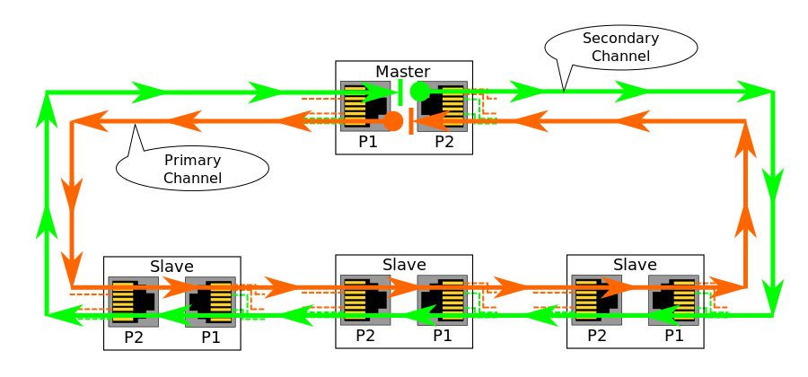 Sercos III Ring Topology |
Read more about SERCOS III here.


JVL A/S Bregnerødvej 127 DK-3460 Birkerød Denmark
Tel: +45 4582 4440 Fax: +45 4582 5550 E-mail: jvl@jvl.dk
Tel: +45 4582 4440 Fax: +45 4582 5550 E-mail: jvl@jvl.dk
